Solid state materials can be grouped in to 3 classes :- Insulators, Conductors and Semiconductors. Semiconductor material is neither conductor nor insulator. It has conductivity between conductors and insulators and is sensitive to temperature, illumination, magnetic field and minute amount of impurity atoms. This type of sensitive material for controlling or switching current is very much required in modern age. Today electronics means present of semiconductor devices.
Semiconductor Devices are the foundation of electronics industry. For Learning electronics it is necessary to have basic knowledge of Semiconductor device. A common semiconductor device is a Transistor.
Aim of this project is to determine characteristic of a NPN transistor by varying base voltage and detect Cut-off Region and Saturation Region. We have used a potentio-meter for varying Base voltage. After assembling the circuit use a digital multi-meter and scale mark the voltage. You can also attach a multi-meter permanently. A low power indicator such as LED is used for detection of conductance of transistor. LED is connected to power supply through collector of transistor so that when transistor is conducted then circuit will be complete and led glows. After making the project. Place the battery and start rotating knob of POT. You will see LED begins glowing reaching 0.5V and at 0.7V it will be at full bright. Thus you can mark cut off region (fully off) and Saturation Voltage (full dark). Most of the transistor will conduct from .5 to .7 Volt. This type of circuit is commonly used in voltage stabilizer for high voltage cut off. A relay is placed at LED connection.
Parts Used
NPN Transistor BC548
Resistance 1K and 220 Ohm
10K POT with knob
LED and Battery Container
Transistor voltage (NPN )
1. As a switch: OFF = 0 to 0.3V, ON=0.7 V (Cutoff and Saturation Region )
The circuit illustrated below can RE use your thrown tube light. which usually blinks in normal circuit. A high DC voltage has advantage to glow a a weak florescent tube light. A weak florescent tube gets black at one edge. At black end Positive voltage should be applied and can be marked as anode and other clear end cathode can be marked for Negative voltage or electron will be supplied.
Please see circuit Diagram.For converting AC to DC we have used a Rectifier Circuit. Choke Should be used in series with rectifier circuit for limiting current.Rectified voltage(DC) is applied to both end of the tube. Circuit Diagram
Part List : Choke or you can use 100W Bulb Diode -IN4007 or 159 X 4pcs
Here is a simple Electronic Switch which can be operated by any Magnetic Field. It can serve purpose of REED Switch with little modification using a relay because it can not directly drive electrical loads as their output drive capabilities are very small around 10 to 20mA. You can also use transistor as current amplifier.
For the simplicity of the circuit I have used few components. In this circuit I have used Hall Effect Sensor, one LED and a 9 Volt battery. 5 Volt is enough for the circuit to operate. In market you will find two types of Hall Effect Sensor, Latching and Non-latching Sensors. In Latching type sensor, output state does not change even when you pull magnet away. In this project I have used Latched Hall Effect Sensor US1881. A electromagnet can also be used to control the circuit from a remote point.
Thermal Electricity Generator, Generate Electric Current using a Candle.
Here is a simple mini project to generate electricity without any mechanical parts i.e. Dynamo, Gear, Turbine etc. Heat is directly converted in to DC current with more efficient and few parts.
Picture of our Thermal power generator
Output power will depend on how much temperature difference you have created across Thermoelectric Peltier so your focus will be to make hot in one side and cool other side. Since metal is good conductor of heat so you can use metal piece to transfer temperature or as a heat sink.
In this project we are able to generate potential difference of 1.5 Volt easily which is enough to drive a low power Fan. You can increase voltage by connecting more Thermoelectric Peltier in series.
Parts used:
TEC1-12706 Thermoelectric Cooler Peltier
Low power motor – which is used in Helicopter, Walkman, small dvd player, vibrator motor of Mobile Phone etc.
Candel
Clamp
Aluminium or Copper Heat sink. easily found in electronics circuit or you can cut a metal peace, you will get it from hardware shop.
Heat-sink Compound. easily available in electronics parts shop or in computer hardware shop. In computer it is pasted between processor and CPU heat sink Fan.
Tips for getting the maximum power from the heat energy
To keep the experiment simple I have made this project roughly (as shown in the video)but you can obtain more power by following this tips. Heat Sink metal should have wings as in picture or at least keep metal surface wide, Keep source of heat as close to the Peltier if not possible then use a metal peace to carry heat to the Peltier. Metal should be tightly fitted to Peltier with screw so spring system and heat sink paste(compound) should be used to fill air gap in between.
An introduction: Needs no manual operation for switching ON and OFF. When there is a need of light it automatically switches ON. When darkness rises to a certain level then sensor circuit gets activated and switches ON and when there is other source of light i.e. daytime, the street light gets OFF. The sensitiveness of the street light can also be adjusted. In our project we have used four L.E.D as a symbol of street lamp, but for high power switching one can connect Relay (electromagnetic switch) at the output of pin 3 of I.C 555 that will make easy to turn ON/OFF any electrical appliances that are connected through relay.
Principle : This circuit uses a popular timer I.C 555. I.C 555 is connected as comparator with pin-6 connected with positive rail, the output goes high(1) when the trigger pin 2 is at lower then 1/3rd level of the supply voltage. Conversely the output goes low (0) when it is above 1/3rd level. So small change in the voltage of pin-2 is enough to change the level of output (pin-3) from 1 to 0 and 0 to 1. The output has only two states high and low and can not remain in any intermediate stage. It is powered by a 6V battery for portable use. The circuit is economic in power consumption. Pin 4, 6 and 8 is connected to the positive supply and pin 1 is grounded. To detect the present of an object we have used LDR and a source of light.
LDR is a special type of resistance whose value depends on the brightness of the light which is falling on it. It has resistance of about 1 mega ohm when in total darkness, but a resistance of only about 5k ohms when brightness illuminated. It responds to a large part of light spectrum. We have made a potential divider circuit with LDR and 100K variable resistance connected in series. We know that voltage is directly proportional to conductance so more voltage we will get from this divider when LDR is getting light and low voltage in darkness. This divided voltage is given to pin 2 of IC 555. Variable resistance is so adjusted that it crosses potential of 1/3rd in brightness and fall below 1/3rd in darkness. Sensitiveness can be adjusted by this variable resistance. As soon as LDR gets dark the voltage of pin 2 drops 1/3rd of the supply voltage and pin 3 gets high and LED or buzzer which is connected to the output gets activated.
Circuit Diagram of Automatic Street Light
Component used :
9v Battery with strip
Switch
L.D.R (Light Depending Resistance)
I.C NE555 with Base
L.E.D (Light Emitting Diode) 3 to 6 pieces.
Variable Resistance of 47 KΩ
P.C.B (Printed Circuit Board of 555 or Vero board.
COMPONENTS : a) Battery: For 9v power supply we can use 6pcs dry cell or 6F22 9v single piece battery. b)Switch: Any general purpose switch can be used. A switch is used as a circuit breaker. c) L.D.R: (Light Depending Resistance) it is a special type of resistance whose value depends on the brightness of light which is falling on it. It has a resistance of about 1mega ohm when in total darkness, but a resistance of only about 5k ohms when brightness illuminated. It responds to a large part of light spectrum. d) L.E.D: (Light Emitting Diode) A diode is a component that only allows electricity to flow one way. It can be thought as a sort of one way street for electrons. Because of this characteristic, diode are used to transform or rectify AC voltage into a DC voltage. Diodes have two connections, an anode and a cathode. The cathode is the end on the schematic with the point of the triangle pointing towards a line. In other words, the triangle points toward that cathode. The anode is, of course, the opposite end. Current flows from the anode to the cathode.
Light emitting diodes, or LEDs, differ from regular diodes in that when a voltage is applied, they emit light. This light can be red (most common), green, yellow, orange, blue (not very common), or infa red. LEDs are used as indicators, transmitters, etc. Most likely, a LED will never burn out like a regular lamp will and requires many times less current. Because LEDs act like regular diodes and will form a short if connected between + and -, a current limiting resistor is used to prevent that very thing. LEDs may or may not be drawn with the circle surrounding them.
e) Variable resistance: (Potentiometer) Resistors are one of the most common electronic components. A resistor is a device that limits, or resists current. The current limiting ability or resistance is measured in ohms, represented by the Greek symbol Omega. Variable resistors (also called potentiometers or just “pots”) are resistors that have a variable resistance. You adjust the resistance by turning a shaft. This shaft moves a wiper across the actual resistor element. By changing the amounts of resistor between the wiper connection and the connection (s) to the resistor element, you can change the resistance. You will often see the resistance of resistors written with K (kilohms) after the number value. This means that there are that many thousands of ohms. For example, 1K is 1000 ohm,2K is 2000 ohm, 3.3K is 3300 ohm, etc. You may also see the suffix M (mega ohms). This simply means million. Resistors are also rated by their power handling capability. This is the amount of heat the resistor can take before it is destroyed. The power capability is measured in W (watts) Common wattages for variable resistors are 1/8W, 1/4W, 1/2W and 1W. Anything of a higher wattage is referred to as a rheostat f) PCB (Printed Circuit Board) with the help of P.C.B it is easy to assemble circuit with neat and clean end products. P.C.B is made of Bakelite with surface pasted with copper track-layout. For each components leg, hole is made. Connection pin is passed through the hole and is soldered. WORKING: When light falls on the LDR then its resistance decreases which results in increase of the voltage at pin 2 of the IC 555. IC 555 has got comparator inbuilt, which compares between the input voltage from pin2 and 1/3rd of the power supply voltage. When input falls below 1/3rd then output is set high otherwise it is set low. Since in brightness, input voltage rises so we obtain no positive voltage at output of pin 3 to drive relay or LED, besides in poor light condition we get output to energize. Precautions: a) Use a Sensitive LDR. You can test it using a multimeter. b) I.C should not be heated too much while soldering, excess heat can destroy it. For safety and easy to replace, use of I.C base is suggested. While placing the I.C pin no 1 should be made sure at right hole. c) Opposite polarity of battery can destroy I.C so please check the polarity before switching ON the circuit. One should use diode in series with switch for safety since diode allows flowing current in one direction only. d) L.E.D glows in forward bias only so incorrect polarity of L.E.D will not glow. Out put voltage of our project is 7.3 volt therefore 4 LED in series can be easily used with out resistance. e) Each component should be soldered neat and clean. We should check for any dry soldered. f) LDR should be so adjusted that it should not get light from streetlight itself.
Presented here is a microcontroller-based project for tracking a vehicle using global positioning system (GPS) and global system for mobile communication (GSM). --subham rajak Presented here is a GPS based vehicle tracking system based on the ATMega16 microcontroller using global positioning system (GPS) and global system for mobile communication (GSM).
This is a cheaper solution than a two-way GPS communication system wherein communication is done in both ways with GPS satellites. This project uses only one GPS device and two-way communication is achieved using a GSM modem. GSM modem with a SIM card used here implements the same communication technique as in a regular cellphone. The system can be mounted or fitted in your vehicle in a hidden or suitable compartment. After this installation, you can easily track your vehicle using your mobile phone by dialling the mobile number of the SIM attached to the GSM modem. You will automatically get the location of the vehicle in the form of an SMS (short message) on your mobile phone.
This system allows you to track your vehicle anytime and anywhere. Whether you own a company with a fleet of hundreds of vehicles or you have expensive piece of equipment and you want to keep an eye on them, this tracking system can inform you of the status without you having to be actually present on the site.
Fig. 1 shows the block diagram of the GSM and GPS based vehicle tracking system.
Applications and benefits
1. You can locate your stolen vehicle easily using your mobile without any extra cost.
2. It can be used for trucks carrying valuable goods, to keep track of the status of delivery and location of the truck at all times.
3. The device ensures vehicle security and smooth fleet management.
4. You can easily install it in any vehicle such as cars, boats and motorbikes. An SMS will inform you whether the vehicle is stationary or on the move.
5. You can also use it to keep tab on your driver. It reduces vehicle abuse and ultimately results in significant cost-savings for individuals, fleet owners and the like.
Before delving into the detailed working of the project, let’s discuss some basics of GPS and GSM technologies.
GPS
GPS is a space-based satellite navigation system. It provides location and time information in all weather conditions, anywhere on or near the Earth. GPS receivers are popularly used for navigation, positioning, time dissemination and other research purposes.
The GPS consists of satellites that orbit the earth. These satellites are geosynchronous with an orbital period that is the same as the Earth’s rotation period. So they maintain exactly the same position with respect to the earth below them. All the GPS satellites transmit radio signals, which are then captured by a GPS receiver and used to calculate its geographical position. A minimum of four satellites may be required to compute the four dimensions of X, Y, Z (latitude, longitude and elevation) and time. GPS receiver converts the received signals into position and estimates time and some other useful information depending on the application and requirements.
GPS determines the distance between a GPS satellite and a GPS receiver by measuring the amount of time taken by a radio signal (the GPS signal) to travel from the satellite to the receiver. To obtain accurate information, the satellites and the receiver use very accurate clocks, which are synchronised so that they generate the same code at exactly the same time.
If accuracy is important, you need GPS with a wide-area augmentation system (WAAS) capability. This is a satellite service providing additional correction information to the GPS receiver in order to increase its accuracy.
Before purchasing a GPS receiver, it’s good to know the protocols supported by it. Some popular protocols for GPS receivers are:
NMEA 0183
An industry-standard protocol common to marine applications defined by National Marine Electronics Association (NMEA), USA. NMEA provides direct compatibility with other NMEA-capable devices such as chart plotters and radars.
TSIP (trimble standard interface protocol)
A binary packet protocol that allows the designer to configure and control the GPS receiver for optimal performance in any number of applications.
TAIP (trimble ASCII interface protocol)
Designed specifically for vehicle tracking applications. It is a bidirectional protocol using simple ASCII commands with the associated ASCII responses.
GSM modem
GSM is a standard set developed by the European Telecommunications Standards Institute (ETSI) to describe technologies for second-generation (2G) digital cellular networks.
A GSM modem is a specialised type of modem that accepts a SIM card and operates over a subscription to a mobile operator just like a mobile phone.
GSM modems are a cost-effective solution for receiving SMS messages because the sender is paying for the message delivery. To perform these tasks, a GSM modem must support an extended AT command set for sending and receiving SMS messages, as defined in the ETSI GSM 07.05 and 3GPP TS 27.005 specifications.
It should also be noted that not all phones support this modem interface for sending and receiving SMS messages, particularly most smartphones like the Blackberry, iPhone and Windows mobile devices.
GPS based vehicle tracking system: Circuit description
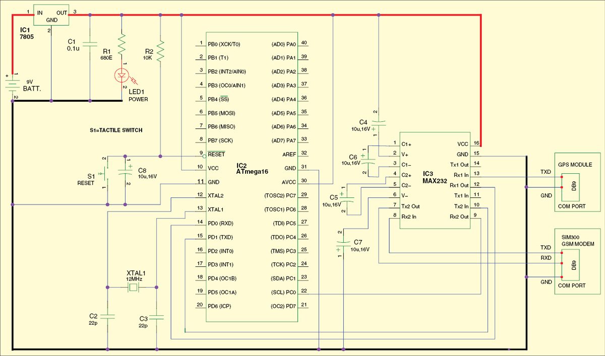
Fig. 2 shows the circuit of a GSM and GPS based vehicle tracking system. It consists of a microcontroller, GPS module, GSM modem and 9V DC power supply. GPS module gets the location information from satellites in the form of latitude and longitude. The microcontroller processes this information and sends it to the GSM modem. The GSM modem then sends the information to the owner’s mobile phone.
ATmega16 microcontroller
ATmega16 microcontroller (IC2) is the heart of the project that is used for interfacing to various hardware peripherals. It is a low-power CMOS 8-bit microcontroller based on the AVR enhanced RISC architecture.
ATmega16 microcontroller is interfaced serially to a GPS module and GSM modem. The GPS module outputs many data but in this project only the NMEA data is read and processed by the microcontroller. The processed data is sent to the user’s mobile through a GSM modem.
This GPS based vehicle tracking system implements RS-232 protocol for serial communication between the microcontroller, GPS and GSM modem. A serial driver IC MAX232 (IC3) is used for converting RS-232 voltage levels into TTL voltage levels.
The user’s mobile number should be included in the source code written for the microcontroller. Thus the user’s mobile number resides in the internal memory of the MCU.
iWave GPS module
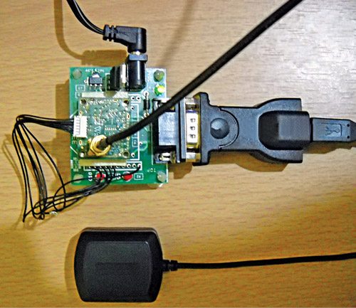
In this project, we have used the iWave GPS module (refer Fig. 3). GPS always transmits the data to the microcontroller. Transmit pin TXD of GPS is connected to the microcontroller via MAX232. NMEA defined an RS-232 communication standard for devices that include GPS receivers. The iWave GPS module supports the NMEA-0183 standard that is a subset of the NMEA protocol. It operates in the L1 frequency (1575.42 MHz) and provides information with accuracy of up to 10 metres in open sky. Antenna should be placed in the open space and there should be at least 50 per cent space visibility.
GSM modem
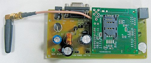
This GPS based vehicle tracking system uses SIM300 GSM modem (refer Fig. 4). GSM modem transmits and receives the data. Modem SIM300 is a tri-band GSM/GPRS engine that works on frequencies EGSM 900 MHz, DCS 1800 MHz and PCS 1900 MHz.
Transmit pin TXD and receive pin RXD of GSM modem are connected to the microcontroller (IC2) via MAX232 (IC3). Port pin PD0 (RXD) and port pin PD1 (TXD) of the microcontroller are connected to pins 12 and 10 of MAX232, respectively.
Power supply. The circuit is powered off a 9V battery. 7805 regulator (IC1) is used to convert 9V into 5V. The microcontroller and MAX232 are powered by 5V. LED1 indicates the presence of power supply.
Software program
The program for the microcontroller is written in ‘C’ language and compiled using AVR Studio. The user’s mobile number should be included in the source code in order to receive the call from the SIM card used in the GSM modem. The hex code of the program is burnt into the MCU using PonyProg2000 software. You can use any other suitable tool for the same.
GPS module with 9600 baud rate is used to receive the data from the satellites, which is defined in the software. The software is developed to decode the NMEA protocol. This protocol includes a set of messages that use ASCII character set and have a defined format that are continuously sent by the GPS module to the interfacing device.
The GPS module or receiver provides data in the form of ASCII comma-delimited message strings. Each message starts with a dollar sign ‘$’ (hex 0x24) and ends with (hex 0x0D 0x0A).
Download PCB and Component Layout PDFs: click here
The software output protocol message includes global positioning system fixed data (GGA) and geographic position latitude/longitude (GLL). In this project, we will use GGA only.
Note that the latitude and longitude information are both represented in the ‘degrees, minutes and decimal minutes’ format as ddmm.mmmm. However, most mapping applications require longitude and latitude to be expressed in decimal, degrees, in ‘dd.dddddd’ format with a corresponding sign (negative for south latitude and west longitude). So some kind of conversion is required in the software if you want a particular format.
The NMEA standard explains how each message string is formed with a dollar sign ($) leading each new GPS message.
or example: $GPGGA,002153.000,3342.6618,N,11751.3858,W where $GPGGA is the GGA protocol header, 002153.000 is UTC time in hhmmss.ss format, 3342.6618 is the latitude of the GPS position fixed data in ddmm.mmmm format, 11751.3858 is the longitude of the GPS position fixed data in dddmm.mmmm format, and ‘N’ stands for North and ‘W’ for West.
With this data you can find out the exact location using a map or you can use freely available software to check the location.
Construction and testing
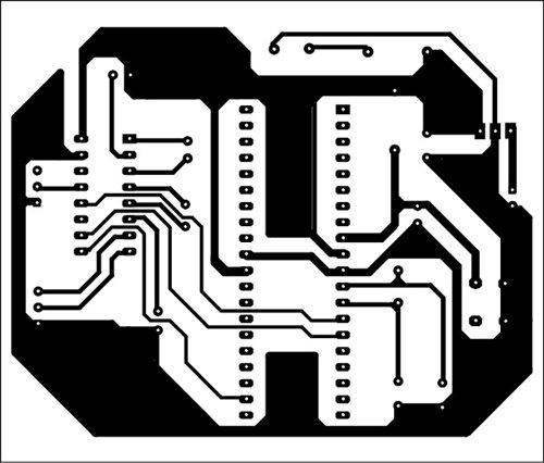
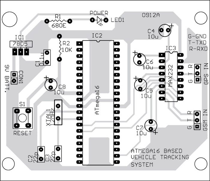
An actual-size, single-side PCB layout of the GPS and GPS based vehicle tracking circuit is shown in Fig. 5 and its component layout in Fig. 6.
Assemble the components on the PCB with IC bases for ATmega16 and MAX232. Burn the code into the MCU and mount it on the PCB. Insert the SIM card with sufficient balance in the GSM module. Connect the circuit as shown in Fig. 2.
Testing
1. Connect the circuit to GPS and GSM modem as shown in Fig. 2.
2. Switch on the circuit and you will see LED1 glow.
3. Switch on the GPS module and wait for 10-15 minutes for initialisation.
4. Switch on the GSM modem.
5. Dial the mobile number in the GSM modem. After two rings, the ringing stops automatically. Wait for a few seconds. You will get an SMS alert in your mobile.
6. Check your SMS inbox. You will see the latitude and longitude data in the form of SMS text.
7. Open a standard map and locate the point on the map. You can also enter latitude and longitude values in a software such as on http://www.latlong.net/Show-Latitude-Longitude.html or any other suitable software.
to see the result of the project see the video
Further applications This system can also be used where the information is not needed so frequently and the subject has to be tracked at irregular time periods, such as monitoring of adolescents by parents, in research to track animals in the jungle, coordinating search and rescue efforts, and mapping trails and exploring new terrains.
Rain detector circuit is the device which will really work as you wish what you want to do. It is a device which will generate the signal when the rain comes. The frequency will be more when the rain is heavier and the frequency is very less when the rain will be low. It all means that the frequency will depend on the rain. We always should focus on the signal making. Don’t focus on the rest of the part which we have to make it. When we get the signal now we can do anything we want to do.
We will make a single wire circuit so that the circuit is easy and every reader can read it. Double wired is quite complicated and the circuit which is made has to be with an IC’s so I will prefer today to show you with a single cable and for the complicated circuit you may go to the article how to make a rain detector with IC’s.
1st experiment:
As you know that not a single machine is made with having all facilities in the first attempt so here it goes.
This is the easiest circuit that you have ever seen. In the practice of school, this is done in 5th or 6th class. It is very easy to make and only a few cheapest thing is required.
Aim: To make rain detector.
Material required:
LED, connecting wire, battery and a zigzag switch like in calculator.
Procedure:
1.Connect everything as you can. I hope that you can glow the led by connecting the wire. And you will not see in the pitcher for help you can see this picture.
2.Prepare rain detector probe. For that only connect the wire on the two end of the switch.
3.Connect wire of that length so that the detector reaches your roof.
4.Cut the wire of the led circuit from anywhere.
5.Connect the detector in the terminals of the led circuit.
6.Now when the rain will come or the detector pad becomes wet by any source then the circuit will glow
We have made a circuit that will work according to the rain. But there are a lot of disadvantage on this circuit.
Advantages:
1.It is very cheap.
2.The battery lasts very much.
3.Not risky.
4.No harmful effect.
5.The circuit can be made by everyone.
Disadvantages:
1.It doesn’t tell about the speed of the rain which is fallen on the roof.
2.It will send a signal or the led will be glowing until the detector becomes wet.
3.It something is over that then the detector will not work until it gets wet.
4.There is so many problems that you will face when you will make this circuit.