Friday, 30 March 2018

Constructional Timer Projects

Timer circuit has been used in many projects and there are basically 2 types that are used these days. One of them is the use of analog RC circuit where charging of the capacitor circuit determined the T of the circuitry. This type of circuitry has larger tolerance and is used in applications where the T is not so critical as the T is affected by the tolerance of the RC components used.

The other is the use of crystal or ceramic resonators together with microprocessor, micro controller or application specific integrated circuit that need higher precision T in the tolerance of up to 5 ppm (parts per million).


555 IC
One commonly used circuit is the 555 IC which is a highly stable controller capable of producing timing pulses. With a monostable operation, the T(time) delay is controlled by one external resistor and one capacitor. With an astable operation, the frequency and duty cycle are accurately controlled by two external resistors and one capacitor.The application of this integrated circuit is in the areas of PRECISION TIMING, PULSE GENERATION, TIMING DELAY GENERATION and SEQUENTIAL TIMING.
A typical 555 IC block diagram is as shown below.
Monostable Operation
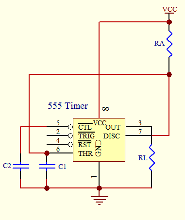
Figure below shows the monostable operation of a 555 IC.

555 Timer Monostable Circuit
In this mode, the device generates a fixed pulse whenever the trigger voltage falls below Vcc/3. When the trigger pulse voltage applied to pin 2 falls below Vcc/3 while the its output is low, its internal flip-flop turns the discharging transistor Tr off and causes the output to become high by charging the external capacitor C1 and setting the flip-flop output at the same instant.
The voltage across the external capacitor C1, VC1 increases exponentially with the T constant T=RA*C1 and reaches 2Vcc/3 at td=1.1RA*C1. Hence, capacitor C1 is charged through resistor RA. The greater the time constant RA*C1, the longer it takes for the VC1 to reach 2Vcc/3. In other words, the time constant RA*C1 controls the output pulse width. When the applied voltage to the capacitor C1 reaches 2Vcc/3, the comparator on the trigger terminal resets the flip-flop, turning the discharging transistor Tr on. At this time, C1 begins to discharge and its output goes to low.
Astable Operation 

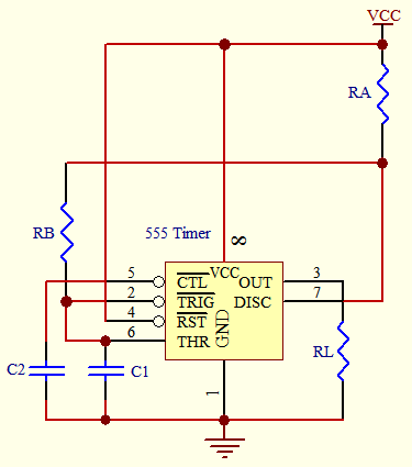
555 Timer Astable Circuit
An astable operation is achieved by configuring the circuit as shown above. In the astable operation, the trigger terminal and the threshold terminal are connected so that a self-trigger is formed, operating as a multivibrator. When its output is high, its internal discharging transistor Tr turns off and the VC1 increases by exponential function with the time constant (RA+RB)*C.
When the VC1, or the threshold voltage, reaches 2Vcc/3, the comparator output on the trigger terminal becomes high, resetting the F/F and causing its output to become low. This in turn turns on the discharging transistor Tr and the C1 discharges through the discharging channel formed by RB and the discharging transistor Tr. When the VC1 falls below Vcc/3, the comparator output on the trigger terminal becomes high and the tmr. output becomes high again. The discharging transistor Tr turns off and the VC1 rises again. The frequency of oscillation is given as below. 

Frequency, f = 1/T = 1.44/[(RA + 2RB)C1]

Thursday, 9 November 2017

Temperature Display Using LCD

Here is a Simple Temperature Display Circuit using LCD (Liquid Crystal Display). For Heat Sensor we have used IC LM35 (Precision Centigrade Temperature Sensors) whose Output voltage is linearly proportional to the Celsius (Centigrade) temperature. Output of LM35 IC is 10mv/degree centigrade for eg if temperature is 35 degree, then the output of sensor will be 350mv or 0.35V
For working with LCD it is necessary to have Microprocessor. We have used Arduino Controller Board, which is AN OPEN-SOURCE ELECTRONICS PROTOTYPING PLATFORM.
Output of LM35 is feed to Arduino Analog input pin 0.
Further Data is Processed by the C Program. Output of Micro-controller is connected to the 16X2 LCD
Digital Temperature Display using 16X2 LCD
Picture of Digital Thermometer
Below is the Simple Programme which is used here :-

#include <LiquidCrystal.h>
LiquidCrystal lcd(12, 11, 5, 4, 3, 2);
const int inPin = 0;
void setup()
{
lcd.begin(16, 2);
}
void loop()
{
int x = analogRead(inPin);
lcd.setCursor(0, 1);
float millivolts = (x / 1024.0) * 5000;
float celsius = millivolts / 10;
lcd.clear();
lcd.setCursor(0,0);
lcd.print(celsius);
lcd.print(” C”);
lcd.setCursor(0,1);
lcd.print((celsius * 9)/ 5 + 32);
lcd.print(” F”);
delay(1000);
}

Digital Temperature Display Circuit Diagram
Circuit Diagram of Digital Thermometer
If you are new to Arduino, then follow below Instruction while making this Project :
1. After Buying Arduino Controller Board. Make sure it is working correctly. You have to Install Drive and application Software. You may need to do Jumper Setting on some board to switch between USB and External Power Source. Download arduino 1.0.5 for windows
Download CP2102 USB to UART Bridge Controller Driver.
2. After above steps, open Arduino Software and select correct board type and COM Port (Very Imp) from Menu Tools -> Board . You can identify your Arduino Board by reading main IC number.
3. To make sure above step is completed and all are functioning well, upload a simple Basic programme from the Arduino Library Examples. You have to add one resistance and LED. for eg you can do Blink Programme ( Turns on an LED on for one second, then off for one second) or LED Fade Programme.
4. Next Connect your Arduino Kit to 16X2 LCD. Here you have to add one more part, which is 10K Variable Resistance. You will get absolutely nothing character displayed on LCD if 10K preset is not adjusted correctly. If you are not sure, then adjust it near about .5 Volt and latter it can be fine tuned for better contrast.
5. For easy connection and Preset soldering I recommend use of PCB. which is shown below. You can save this for printing on copper clad Board. You can make your own PCB by Heat Transfer method or by screen printing method otherwise use Dot Matrix Board or Bread Board. This PCB will help you in all projects which used 16X2 LCD by reducing LCD Pin from 16 to 8 for easy connection.

Temperature Sensor

This project uses IC LM35 as a sensor for detecting accurate centigrade temperature. Linearity defines how well over a range of temperature a sensor’s output consistently changes. Unlike thermistor, Linearity of a precision IC Sensors are very good of 0.5°C accuracy and has wide temperature range. its output voltage is linearly proportional to the Celsius (Centigrade) temperature.
the LM35 is rated to operate over a -55° to +150°C temperature range.It draws only 60 µA from its supply, it has very low self-heating, less than 0.1°C in still air. LM35 Operates from 4 to 30 volts.
An output of IC is 10mv/degree centigrade for eg if the output sensor is 280 mV then the temperature is 28 degrees C. so by using a Digital multimeter we can easily calculate the degree temperature. For trigger point, you should set the voltage of pin 2 of IC 741 by using preset or potentiometer.
Our aim of this project is not to construct a thermometer but to activate or deactivate a device at a particular margin temperature. For simplicity, we have used 2 LED for indication of both low (Green) and high (Red) temperature.
Automatic Fan Controller Circuit Diagram
Working: The output of IC2 increases in proportion to the temperature by 10 mV per degree. This varying voltage is fed to a comparator IC 741 (OP Amplifier). OP Amplifier are among the most widely used electronic devices today.The op-amp is one type of differential amplifier. It has two input inverting (-) and non-inverting (+) and one output pin. We have used IC741 as a non-inverting amplifier which means pin 3 is the input and the output is not reversed. This circuit amplifies the difference between its input terminals.
As a comparator, Bistable output of an op amplifier is as follows:-
Part list:
IC LM35, IC LM741
Resistance: 10K Ohms, 470 Ohms X 2Pcs
Preset or P.O.T of 2K Ohms
LED 2pcs (Red and Green)
9V Battery with Snap
Switch, wire
*By making this Temperature Sensor Project, student will be capable of making many similar projects  i.e  Automatic room heater controller, determine hotness of Tea or Coffee to avoid burning your tongue, Automatic Fan Controller etc

Touch Switch

Touch Switch Project
Thief’s are attracted to expensive things when they come in our houses. We can protect our product or thing by making them touch proof or we can stop any unidentified persons entry in our house by making door and window touch proof. This circuit alert us when anyone come to stole products from our house or touch any metallic thing at door / window or in side . We can use this circuit to protect our car or bike by making them touch proof.
as we have describe above this product give alarm when any human body touch any of the metallic thing which are protected by this circuit. This project is working on two transistors which make complimentary pair direct coupled amplifier. This circuit basically is a audio oscillator. For oscillation we use collector of transistor bc558 which is connected to the base of transistor BC548 via resistance 10 k and 0.01 or .02 mfd capacitor . Transistor bc-548 is working as a current amplifier and feedback receiver.
When any human body touch the touch sensor which is connected to base of transistor BC548. This transistor conduct with human skin conductance. When transistor bc-548 start conducting it’s forced to transistor BC558 to start conducting. So we get alarm sound from speaker. When we take back our hand then does not connected to base of transistor bc-548 . So it’s does not conduct we do not get the alarm sound.
Same Circuit can be use as Touch Alarm, Rain Alarm etc
Touch Switch or Rain Alarm Circuit Diagram
Circuit Diagram of Touch Switch / Touch Alarm / Rain Alarm

Traffic Light

Traffic Light Project
Picture of our Traffic Light Project
This Traffic Light Circuit can be used to control traffic on roads or in public places.In a Traffic light there are three different color bulb which are Green, Yellow/Amber and Red.

This project uses  IC555 as Astable Multivibrator for rapid squire wave pulse generation. This clock pulse is feed to IC 4017 which is a Counter IC. In this counter IC, for every pulse fed to input pin-14, the High level output keeps shifting from D1 to D9 in cyclic order. See Circuit Diagram below.
Traffic Light Circuit Diagram
At a time one output is higher (Positive) and other output pins of IC remains at low state.
The capacitor and resistor on pin 15 of IC4017 are used to reset the counter to zero (Red light ON) at initial power up.
Part Used:
IC = NE555 ( Timer IC) , IC CD4017 (Counter IC)
Diode = IN4007 or IN4148  6Pcs
POT = 470K
Resistance = 22K, 100K, 220 Ohms X 3Pcs
Capacitor = 0.1 Mfd, 1 Mfd, 10 Mfd.
LED= Red, Green and Yellow
9 Volt Battery with Snap
Switch, Wire, Clamp, PCB

Transformer

Transformer
Picture of Transformer Model
This is a simple Project for CBSE +2 Students to show how no of turns effects the e.m.f
No. of turns in Primary winding  is _______.
No. of Turns in Secondary winding at each tapping  is _______.
Input Voltage is _________.
Output Voltage in each tapping from common is _________.
In our experiment we have made a Step Down Transformer. In a step down transformer Primary turns is greater than secondary turns. Primary winding of a transformer is always connected to a supply AC source.
For taking input/output voltage  reading of transformer, you can use a voltmeter or Multimeter. For best result use a Digital Multimeter (cost you Rs 120).
For simplicity we have used a small size  12V 2W bulb at output which is commonly used in bike. It glows at every tapping. The brightness increases from lower to higher turns. In my experiment output is from 3V to 12V.
Result: the turns ratio determines the ratio of the voltages in the two coils.
As the volts per turn, which is proportional to the flux in the machine, is the same for the whole winding,
V1 : V2 = T1 : T2
or
V1 / T1 = V2 / T2
You may also be interested in Rectifier Circuit which is generally used with transformer when electronics component is used.

Transistor as a Switch

Transistor as a Switch
                                                       fig. Transistor as a switch
Solid state materials can be grouped in to 3 classes :- Insulators, Conductors and Semiconductors. Semiconductor material is neither conductor nor insulator. It has conductivity between conductors and insulators and is sensitive to temperature, illumination, magnetic field and minute amount of impurity atoms. This type of sensitive material for controlling or switching current is very much required in modern age. Today electronics  means present of semiconductor devices.
Semiconductor Devices are the foundation of electronics industry. For Learning electronics it is necessary to have basic knowledge of Semiconductor device. A common semiconductor device is a Transistor.
Aim of this project is to determine characteristic of a NPN transistor by varying base voltage and detect Cut-off Region and Saturation Region.
We have used a potentio-meter for varying Base voltage. After assembling the circuit use a digital multi-meter and scale mark the voltage. You can also attach a multi-meter permanently.
A low power indicator such as LED is used for detection of conductance of transistor. LED is connected to power supply through collector of transistor so that when transistor is conducted then circuit will be complete and led glows.
After making the project. Place the battery and start rotating knob of POT. You will see LED begins glowing reaching 0.5V and at 0.7V it will be at full bright. Thus you can mark cut off region (fully off) and Saturation Voltage (full dark). Most of the transistor will conduct from .5 to .7 Volt.
This type of circuit is commonly used in voltage stabilizer for high voltage cut off. A relay is placed at LED connection.
Parts Used
NPN Transistor BC548
Resistance 1K and 220 Ohm
10K POT with knob
LED and Battery Container
Transistor voltage (NPN )
1. As a switch: OFF = 0 to 0.3V, ON=0.7 V (Cutoff and Saturation Region )
2. As an Amplifier: 0.5 to 0.7V (Active Region)